Building Your Own Drone - IMU Measurements - Part 3
To maintain stability in the air, Unmanned Aerial Vehicles (UAVs) such as drones rely on sensor fusion, a process that combines data from multiple sensors, including gyroscopes and accelerometers. This enables the UAV to better understand its environment and adjust accordingly
USB communication using STM32 and MPU6050
To begin with, it’s a good step to setup the IMU sensor and do some experiments on its measurements.
- D- (D minus): is part of the “voltage signal differential pair” in the USB communication protocol. In STMCubeIDE this is called “USB_OTG_FS_DM”.
- D+ (D plus): is also part of the “voltage signal differential pair” in the USB communication protocol. In STMCubeIDE this is called “USB_OTG_FS_DP”.
- The reason for using two signals D- and D+ is to reduce noise in the USB communications.
- If the signal changes from 0 to 1 and from 1 to 0 in each clock tick, this means 0 in USB binary.
- If the signal does not change in each clock tick, it means 1 in USB binary.
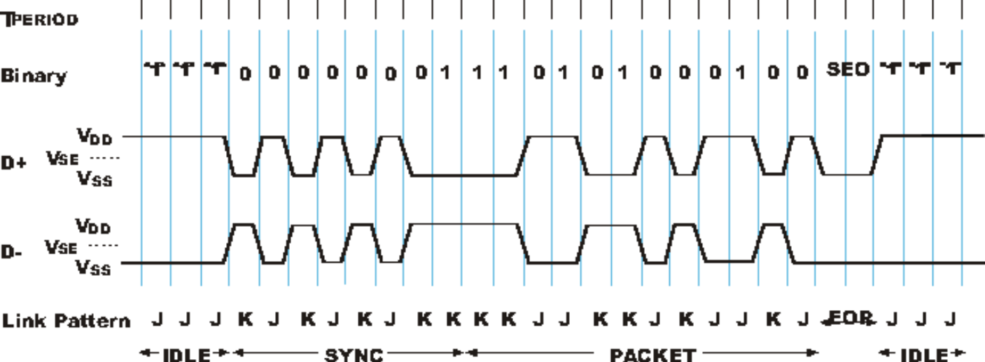
Figure 1: USB data transfer, Link.
Setting up MPU6050 and USB communication in STM32CubeIDE using STM32407G Discovery Board
- Create new project
- Configure all peripherals automatically
- Configure the clocksettings similar to figure 3 below. I choose to have 168MHz. It is very important to have 48MHz for the 48MHz clocks that connects to mains PLL. HSE must be chosen when using USB communication.
- Configure the MPU6050 IMU sensor
- Choose pin PB8 for I2C1 SCL communication to the MPU6050 device as shown in figure 2.
- Choose pin PB7 for I2C1 SDA communication to the MPU6050 device as shown in figure 2.
- Go to connectivity and choose I2C in the I2C dropdown menu under GPIO settings. Also choose Fast Mode under parameter settings in I2C speed mode.
- Configure the USB communication
- Go to Connectivity and choose USB_OTG_FS.
- Go to Mode and choose Device_Only.
- Be sure to check the box for Active_VBUS
- Next, go to Middleware and Software Packs and choose USB_DEVICE
- Under Class For FS IP, choose Communication Device Class (Virtual Port Com)
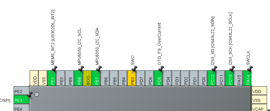
Figure 2: Pin configuration for MPU6050.
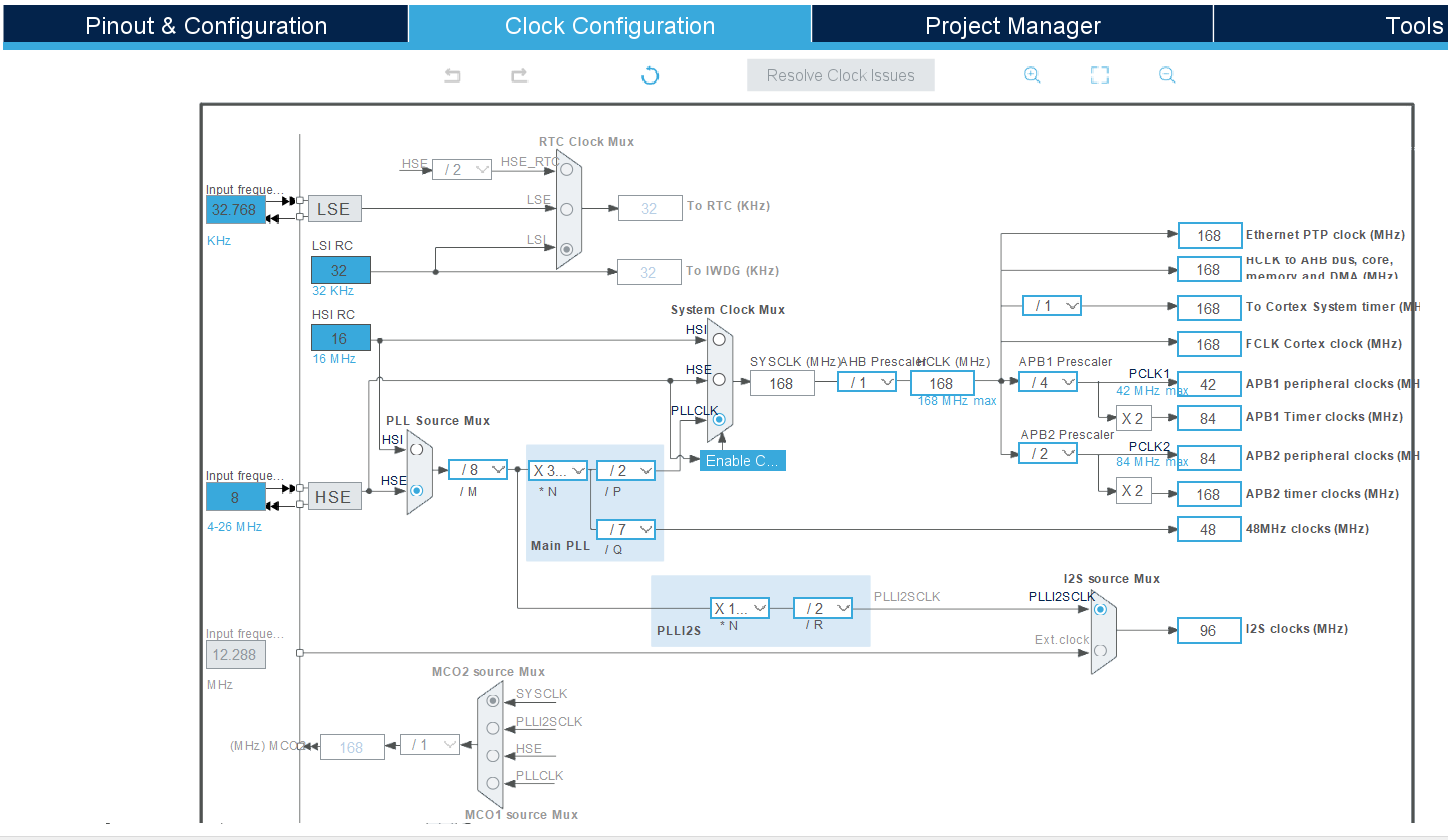
Figure 3: Pin configuration for MPU6050.
Software implementation
- Start by include header files:
/* USER CODE END Header */
/* Includes ------------------------------------------------------------------*/
#include "main.h"
#include "usb_device.h"

/* Private includes ----------------------------------------------------------*/
/* USER CODE BEGIN Includes */
#include "usbd_cdc_if.h"
#include "string.h"
/* USER CODE END Includes */
- Include variables for the USB transfer
/* Private variables ---------------------------------------------------------*/
I2C_HandleTypeDef hi2c1;

I2S_HandleTypeDef hi2s3;

SPI_HandleTypeDef hspi1;

/* USER CODE BEGIN PV */
uint8_t USBRXDataReady = 0;
uint8_t* USBRXDataBuffer;
uint8_t USBRXDataLength = 0;
/* USER CODE END PV */
- Initialize register addresses and variables as in figure 4.
- Make a void function to initialize the MPU6050 IMU sensor as in figure 5.
- Make a void function to read the accelerometer values as in figure 6.
- Make a void function to read the gyroscope values as in figure 7.
- Set up the while loop and run the void functions you made as show in figure 8.
- If you are using sprintf you have to select “use float with printf…” as in figure 9.
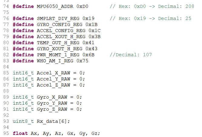
Figure 4: Initialize register addresses and variables for MPU6050.
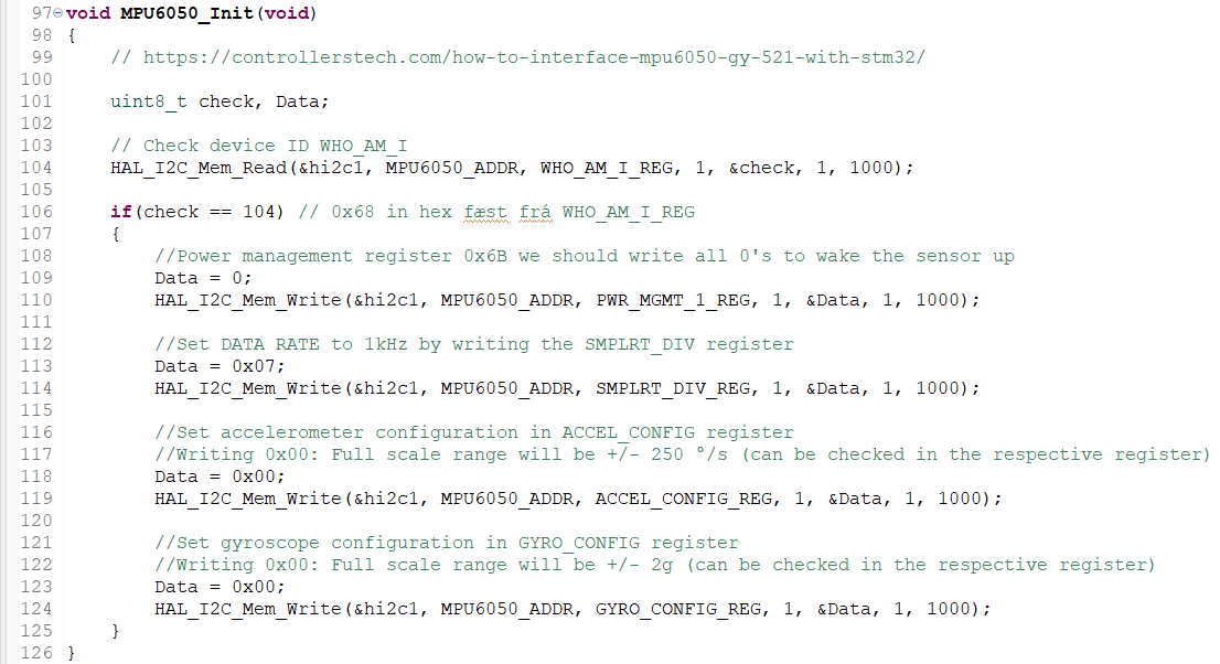
Figure 5: Void function used to initialize the MPU6050 IMU sensor.
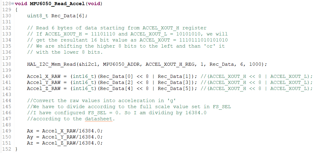
Figure 6: Void function used to read the acceleration values from the MPU6050 IMU sensor.
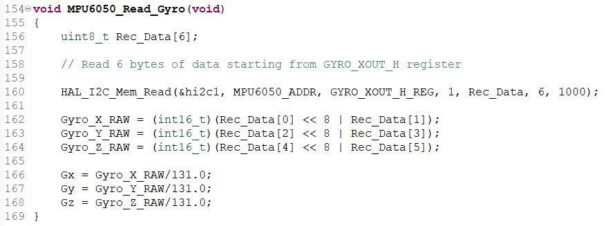
Figure 7: Void function used to read the gyroscope values from the MPU6050 IMU sensor.
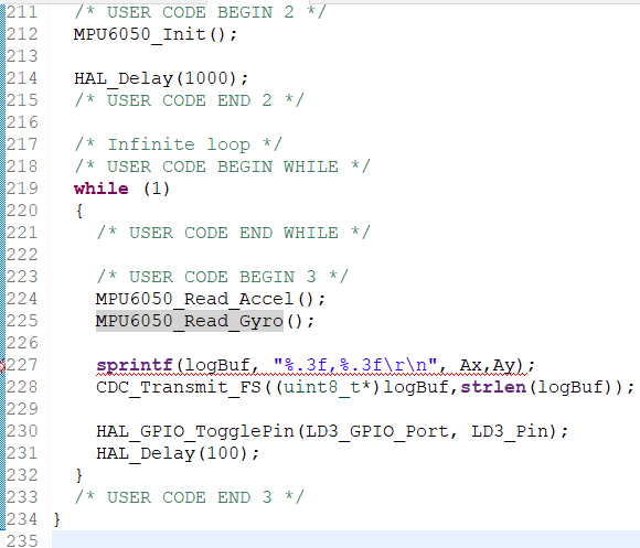
Figure 8: The main loop.
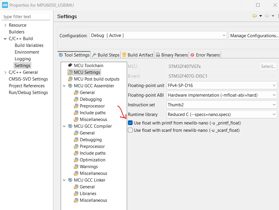
Figure 9: Floating Point with sprintf.
References
[1] USB communication STM32. YouTube. Hamed. Link
[2] Controllerstech Link
[3] Controllerstech Link
[4] Phil’s Lab. I2S ADC DMA. Link
[5] Phil’s Lab. Accelerometer & Gyroscope. Link
[6] Phil’s Lab. Filtering. Link
[7] Phil’s Lab. First Order Low Pass EMA Filter. Link